 |
|
You are here: Foswiki>Amiga Web>A1230TurboSeriesIIClock (11 Jan 2023, BobWicksall)Edit Attach
A1230 Turbo+ Series II Dead Clock
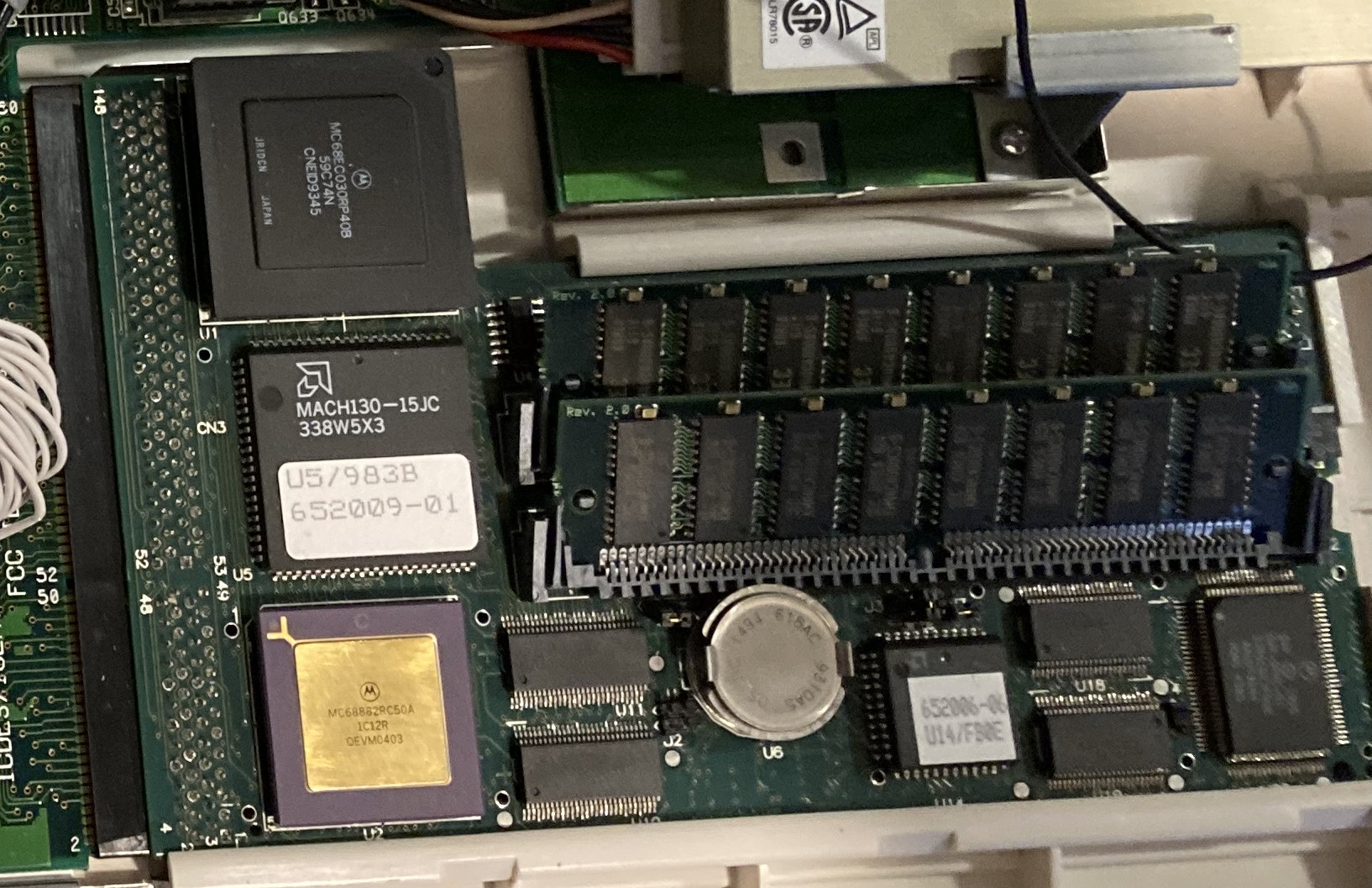
A1230 Turbo+ Series II
Finding a replacement "battery"
The same technology that was used in the Dallas DS1494 is still around and found under the name iButton. There are lots of devices but as far as I can tell just one works. The following works:- DS1994L-F5+ 4kb Time Memory iButton DALLAS/MAXIM
Pop it in your 1200
When I got my DS1994L-F5+ in the mail I immediately popped it in my accelerator. I then set the correct time and rebooted the computer. Boom it worked! Or did it? I quickly realized that while the current time was saved to the clock, the time in the DS1994L-F5+ did not advance. It turns out the clocks are off by default. You need to start the clock before you can use it.Making it work
The following post holds all the answers to working with the DS1994L-F5+. You will need an arduino, a couple of short wires and in my case some painters tape to temporarily attach the wires to the battery. The blog post above shows a more elegant way to wire this up. My attempt is below: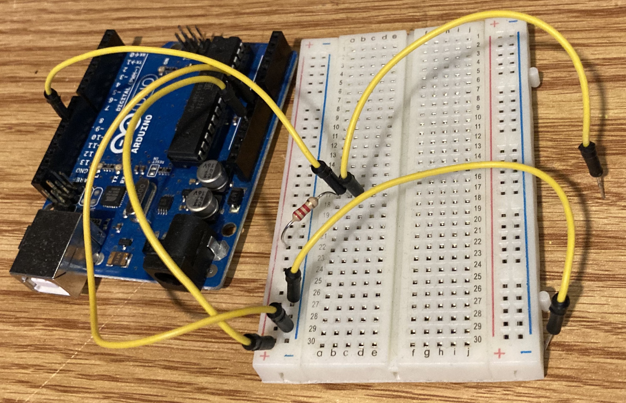
The 2 loose wires on the right were taped to opposite sides of the battery
- 5v and ground to the breakout board.
- A ground jumper for one side of the battery.
- Pin 10 to the breakout board with a 2k resistor pulling it up to 5v and a jumper to the other side of the battery.
#include <OneWire.h>

/*
 * Application example using a DS1994 and the OneWire library
 * Hardware:
 * GND arduino -> Side "outside" of the DS1994
 * VCC 5v arduino -> resistor 4k7 -> D10 arduino
 * D10 arduino -> Side "inside" of DS1994
 */

/* Creating an instance of the OneWire class */
OneWire ds(10); // The DS1994 will be in "parasitic" mode (uses the data bus as a power supply) on pin D10

/* Variables
 * i: iterator for loops
 * data: 5 bytes of data from DS1994
 * addr: address found on the OneWire bus
 * timestamp: number of seconds elapsed
 */
byte i;
byte data[5];
byte addr[8];
unsigned long timestamp;

/* Setup() */
void setup(void) {

  /* Serial port initialization */
  Serial.begin(9600);
  Serial.println("Example DS1994");
}

/* loop() */
void loop(void) {

  /* Search for DSxx present on the OneWire bus */
  Serial.print("Search ... ");
  if (!ds.search(addr)) {
    Serial.println("End of scan");
    ds.reset_search();
    delay(500);
    return;
  }

  /* DSxx ROM display detected */
  Serial.print("ROM : ");
  for(i = 0; i < 8; i++) {
    Serial.write(' ');
    Serial.print(addr[i], HEX);
  }
  Serial.println();

  /* Verification of the validity of the ROM received */
  if (OneWire::crc8(addr, 7) != addr[7]) {
    Serial.println("CRC error on addr");
    return;
  }

  /* Checking the type of DSxx */
  if(addr[0] != 0x04) {
    Serial.println("DSxx of a type other than DS1994");
    return;
  }

  /* Activating the DS1994 oscillator */

  /* Initializing communication with DS1994 */
  ds.reset();
  ds.select(addr);
  ds.write(0x0F, 1); // Commande write scratchpad

  /*
   * The RTC control register is located at address 0x201
   * TA1 et TA2 = LSB / MSB address register
   */
  ds.write(0x01, 1);  // TA1
  ds.write(0x02, 1);  // TA2

  /* Setting the OSC register to 1 */
  ds.write(16, 1);
  ds.reset();

  /* Copy scratchpad to memory */
  ds.reset();
  ds.select(addr);
  ds.write(0x55, 1); // Commande copy scratchpad
  ds.write(0x01, 1); // TA1
  ds.write(0x02, 1); // TA2
  ds.write(0x01, 1); // Offset written in the scratchpad
  ds.reset();

  /* Infinity Loop */
  for(;;) {

    /* Initializing communication with DS1994 */
    ds.reset();
    ds.select(addr);
    ds.write(0xF0, 1); // Commande read memory

    /*
     * Time data starts at 0x202
     * TA1 et TA2 = LSB / Address Register MSB
     */
    ds.write(0x02, 1);  // TA1
    ds.write(0x02, 1);  // TA2

    /* Reading data */
    for(i = 0; i < 5; i++)
      data[i] = ds.read();
    ds.reset();

    /* Converting the raw 4 bytes to a unix timestamp */
    timestamp = data[1];
    timestamp += data[2] << 8;
    timestamp += data[3] << 16;
    timestamp += data[4] << 24;

    Serial.print("Time: ");
    Serial.println(timestamp, DEC);
    delay(1000);
  }
}
Next you will need to add the OneWire library to your Arduino project. Attache the battery, run the code and look at the console output. Your battery should be ready to put back in your GVP accelerator. 

| I | Attachment | Action | Size | Date | Who | Comment |
|---|---|---|---|---|---|---|
| |
Arduino-iButton.jpg | manage | 1 MB | 11 Jan 2023 - 03:31 | BobWicksall | |
| |
GVP1230.jpg | manage | 486 K | 11 Jan 2023 - 02:53 | BobWicksall |
Edit | Attach | Print version | History: r2 < r1 | Backlinks | View wiki text | Edit wiki text | More topic actions
Topic revision: r2 - 11 Jan 2023, BobWicksall
- Toolbox
-
 Index
Index
-
 Search
-
 Changes
-
 Notifications
-
 RSS Feed
Ideas, requests, problems regarding Foswiki? Send feedback